Vector computations are computations where instead of one operation, multiple operations of the same type are performed on several pieces of data at once when a single processor instruction is executed. This principle is also known as SIMD (Single Instruction, Multiple Data). The name arose from an obvious similarity with vector algebra: operations between vectors have single-symbol designations but involve performing multiple arithmetic operations on the components of the vectors.
Originally, vector computations were performed by specialized coprocessors that used to be a major component of supercomputers. In the 1990s, some x86 CPUs and several processors of other architectures were equipped with vector extensions, which are special large-size registers, and the vector instructions to operate them.
Vector instructions are used where there is a need to execute multiple operations of the same type and achieve high computation performance, such as various applications in computational mathematics, mathematical modeling, computer graphics, and computer games. Without vector computations, it is now impossible to achieve the computing performance needed for video signal processing, especially video coding and decoding. Note that in some applications and algorithms, vector instructions do not increase performance.
This article shows examples of using vector instructions and implementing several algorithms and functions that employ them. These examples are mainly taken from the image and signal processing fields but can also be useful to software developers working in other areas of application. Vector instructions help increase performance, but without guaranteed success: to fully realize the potential offered by the computer, the developer needs to be not only careful and precise, but often also inventive.
Instructions and registers
Vector computations are computations where multiple operations of the same type are performed at once when a single processor instruction is executed. This principle is now implemented not only in specialized processors, but also in x86 and ARM CPUs in the form of vector extensions, which are special vector registers that are extra wide compared to general-purpose ones. To work with these, special vector instructions are provided that extend the instruction set of the processor.
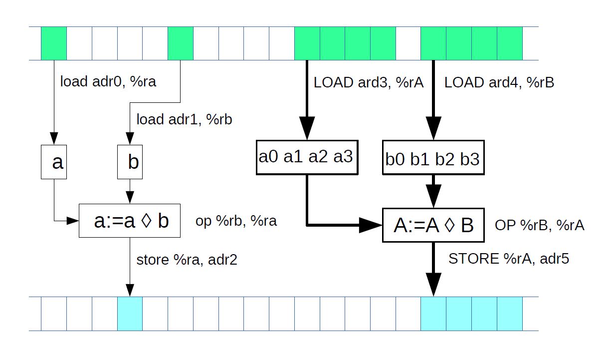
Figure 1: Scalar and vector computations
Normally, vector instructions implement the same operations as scalar, or (regular) instructions (see Fig. 1) but achieve a higher performance due to the higher volume of data they process. A general-purpose register is expected to hold a single data item of a specific type (e.g. an integer of a certain length or a float) when an instruction is executed, while a vector register simultaneously holds as many independent data items of the relevant type as the register can accommodate. When a vector instruction is executed, the same number of independent operations can be performed at once on this data, and the computation performance gets boosted by the same factor. Increasing processor performance by performing multiple identical operations at the same time is the primary purpose of vector extensions.
In x86 CPUs, the first vector extension was the MMX instruction set that used eight 64-bit registers, MM0–MM7. MMX gave way to the more powerful 128-bit SSE float and SSE2 integer and double-precision float instructions that used the XMM0–XMM7 registers. Later, 128-bit SSE3, SSSE3, SSE4.1, and SSE4.2 instruction sets came out that extended SSE and SSE2 with several useful instructions. Most instructions from the above sets use two register operands; the result is written into one of these registers, and its original content is lost.
The next milestone in the development of vector extensions was marked by the even more powerful 256-bit AVX and AVX2 instructions that use the 256-bit YMM0–YMM15 registers. Notably, these instructions use three register operands: two registers store the source data, while the third register receives the operation result, and the contents of the other two remain intact. The most recent vector instruction set is AVX-512 which uses thirty-two 512-bit registers, ZMM0–ZMM31. AVX-512 is used in some server CPUs for high-performance computations.
With the proliferation of 64-bit CPUs, the MMX instruction set was obsolete. However, the SSE and SSE2 instructions did not fall into disuse with the advent of AVX and AVX2 and are still actively used. x86 CPUs maintain reverse compatibility: if the CPU supports AVX2, it also supports SSE/SSE2, SSE3, SSSE3, SSE4.1, and SSE4.2. Similarly, if the CPU supports SSSE3, for example, it supports all the earlier instruction sets.
For ARM CPUs, the NEON vector extension was developed. These 64- and 128-bit vector instructions use thirty-two 64-bit registers or sixteen 128-bit ones (ARM64 has thirty-two 128-bit registers).
Since vector instructions are tied to a specific processor architecture (and often even to a specific processor), programs that use these instructions become non-portable. Therefore, multiple implementations of the same algorithm using different instruction sets become necessary to achieve portability.
Intrinsics
How can a developer use vector instructions? First of all, they can be used in assembler code.
It is also possible to access vector instructions from a program written in a high-level language, including C/C++, without using inline assembler code. To that end, the so-called intrinsics are used, which are embedded compiler objects. One or multiple data types are declared in the header file, and a variable of one of those types corresponds to a vector register. (From the programming point of view, this is a special kind of fixed length array that does not allow access to the individual array elements.) The header file also declares functions that accept arguments and return values of the above types and perform the same operations on data from the programming perspective as the corresponding vector operations. In reality, these functions are not implemented in software: instead, the compiler replaces each call to them with a vector instruction when generating object code. Intrinsics thus allow a program to be written in a high-level language with a performance close or equal to that of an assembler program.
All that is needed to use intrinsics is to include the corresponding header file and when some compilers are used corresponding compiler options should be enabled. Although they are not part of C/C++ language standards, intrinsics are supported by the mainstream compilers such as GCC, Clang, MSVC, Intel.
They also help streamline the processing of various data types. Note that the processor, at least when it comes to the x86 CPU architecture, does not have access to the type of data stored in a register. When a vector instruction is executed, its data is interpreted as having a specific type associated with that instruction, such as float or integer of a certain size (signed or unsigned). It is the developer's responsibility to ensure the validity of the computations, which requires considerable care, particularly as the data type can sometimes change: for example, with integer multiplication, the size of the product is equal to the combined size of the multipliers. Intrinsics can ease the task somewhat.
Thus, the XMM vector registers (SSE) have three associated data types [1]:
__m128, an "array" of four single-precision floats
__m128d, an "array" of two double-precision floats
__m128i, a 128-bit register that can be considered an "array" of 8-, 16-, 32-, or 64-bit numbers. Since a specific vector instruction works typically with only one of the three data types (single-precision float, double-precision float, or integer), the arguments of the functions representing vector instructions also have one of the above three types. The AVX2 type system has a similar design: it provides the types __m256 (float), __m256d (double), and __m256i (integer).
The NEON intrinsics implement an even more advanced type system [2] where a 128-bit register is associated with the types int32x4_t, int16x8_t, int8x16_t, float32x4_t, and float64x2_t. NEON also provides multi-register data types, such as int8x16x2_t. In this kind of system, the specific type and size of register contents are known at all times, so there is less room for error when type conversion occurs and the data size changes.
Consider an example of a simple function implemented using the SSE2 instruction set.
// 1.2.1: Example of SSE2 intrinsics
// for int32_t
#include <stdint.h>
// for SSE2 intrinsics
#include <emmintrin.h>
void bar(void)
{
int32_t array_a[4] = {0,2,1,2}; // 128 bit
int32_t array_b[4] = {8,5,0,6};
int32_t array_c[4];
__m128i a,b,c;
a = _mm_loadu_si128((__m128i*)array_a); // loading array_a into register a
b = _mm_loadu_si128((__m128i*)array_b);
c = _mm_add_epi32(a, b); // must be { 8,7,1,8 }
_mm_storeu_si128((__m128i*)array_c, c);
}
In this example, the contents of array_a is loaded into one vector register and the contents of array_b into another. The corresponding 32-bit register elements are then added together, and the result is written into a third register and finally copied to array_c. This example highlights another notable feature of intrinsics. While _mm_add_epi32 takes two register arguments and returns one register value, the paddd instruction corresponding to _mm_add_epi32 has only two actual register operands, one of which receives the operation result and therefore loses its original contents. To preserve the register contents when compiling the "c = _mm_add_epi32(a, b)" expression, the compiler adds operations that copy the data between registers.
The names of intrinsics are chosen so as to improve source code readability. In the x86 architecture, a name consists of three parts: a prefix, an operation designation, and a scalar data type suffix (Fig. 2, а). The prefix indicates the vector register size: _mm_ for 128 bits, _mm256_ for 256 bits, and _mm512_ for 512 bits. Some data type designations are listed in Table 1. The NEON intrinsics in ARM have a similar naming pattern (Fig. 2, b). Recall that there are two types of vector registers (64- and 128-bit). The letter q indicates that the instruction is for 128-bit registers.
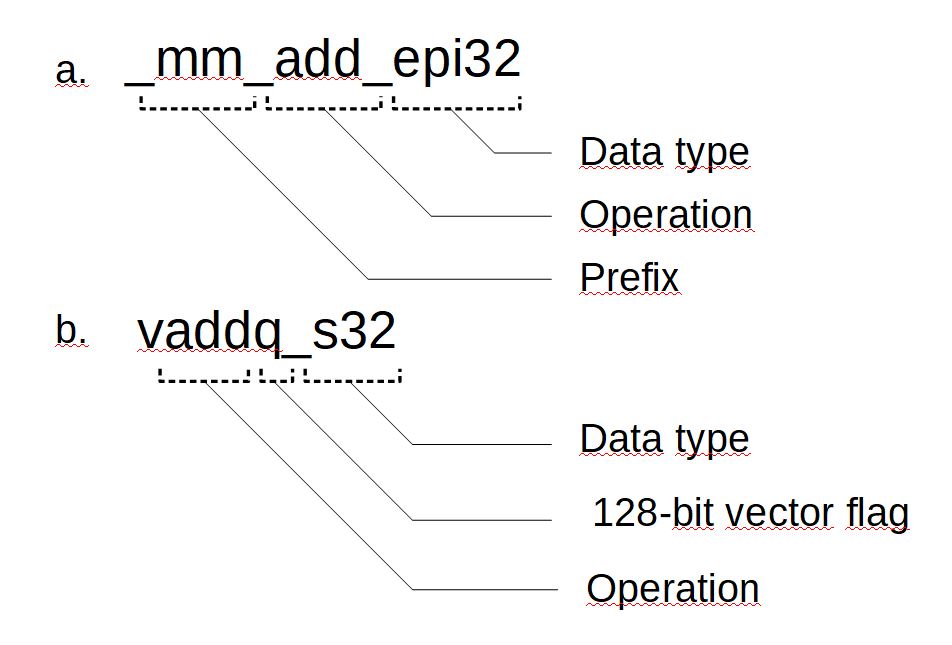
Figure 2: Names of intrinsics in SSE2 (a) and ARM NEON (b)
Table 1: Data type designations for x86 intrinsics
| Disignation | Discription |
| ps | Single-precision float |
| pd | Double-precision float |
| epi8 | 8-bit single integer |
| epu8 | 8-bit unsingle integer |
| epi16 | 16-bit single integer |
| epi32 | 32-bit single integer |
| epi64 | 64-bit single integer |
| si128 | 128-bit single integer |
| si256 | 256-bit single integer |
The names of the intrinsic data types (__m128i and others) and functions have become a de facto standard in different compilers. In the remainder of this text, vector instructions will be referred to by their intrinsic names rather than mnemonic codes.
Essential vector instructions
This section describes the essential instruction classes. It lists examples of frequently used and helpful instructions—mainly from the x86 architecture but also from ARM NEON.
Data exchange with RAM
Before the processor can do anything with data residing in the RAM, the data first has to be loaded into a processor register. Then, after the processing, the data needs to be written back into the RAM.
Most vector instructions are register-to-register—that is, their operands are vector registers, and the result gets written into the same registers. There is a range of specialized instructions for data exchange with RAM.
The _mm_loadu_si128(__m128i* addr) instruction retrieves a 128-bit long continuous array of integers with a start address of addr from the RAM and writes it into the selected vector register. In contrast, the _mm_storeu_si128(__m128i* addr, __m128i a) instruction copies a 128-bit continuous array of data from the register a into the RAM, starting from the address addr. The address used with these instructions, addr, can be arbitrary (but, of course, should not cause array overruns on read and write). The _mm_load_si128 and _mm_store_si128 instructions are similar to the above ones and potentially more efficient but require that addr be a multiple of 16 bytes (in other words, aligned to a 16-byte boundary); otherwise, a hardware exception will be thrown when executing them.
Specialized instructions exist for reading and writing single- and double-precision floating point data (128-bit long), namely _mm_loadu_ps/_mm_storeu_ps and _mm_loadu_pd/_mm_storeu_pd.
A frequent need is to load less data than the vector register accommodates. To that end, the _mm_loadl_epi64(__m128i* addr) instruction retrieves a continuous 64-bit array with the start address of addr from the RAM and writes it into the least significant half of the selected vector register, setting the bits of the most significant half to zeros. The _mm_storel_epi64(__m128i* addr, __m128i a) instruction, which has the reverse effect, copies the least significant 64 bits of the register into the RAM, starting from the address addr.
The _mm_cvtsi32_si128(int32_t a) instruction copies a 32-bit integer variable into the least significant 32 bits of the vector register, setting the rest to zeros. The _mm_cvtsi128_si32(__m128i a) instruction works in the opposite direction by copying the least significant 32 bits of the register into an integer variable.
Logical and comparison operations
The SSE2 instruction set provides instructions that perform the following logical operations: AND, OR, XOR, and NAND. The respective instructions are named _mm_and_si128, _mm_or_si128, _mm_xor_si128, and _mm_andnot_si128. These instructions are fully analogous to the corresponding integer bitwise operations, with the difference being that the data size is 128 bits instead of 32 or 64.
The frequently used _mm_setzero_si128() instruction that sets all the bits of the target register to zeros is implemented using the XOR operation where the same register is used for both operands.
Logical instructions are closely related to comparison instructions. These compare the corresponding elements of two source registers and check if a specific condition (equality or inequality) is satisfied. If the condition is satisfied, all the bits of the element in the target register are set to ones; otherwise, they are set to zeros. For example, the _mm_cmpeq_epi32(__m128i a, __m128i b) instruction checks if the 32-bit elements of the registers a and b are equal to each other. The results of several different condition checks can be combined using logical instructions.
Arithmetic and shifting operations
This group of instructions is, without doubt, the most commonly used.
For floating-point calculations, both x86 and ARM have instructions that implement all four arithmetic operations and square root computation for single- and double-precision numbers. The х86 architecture has the following instructions for single-precision numbers: _mm_add_ps, _mm_sub_ps, _mm_mul_ps, _mm_div_ps, and _mm_srqt_ps.
Let us consider a simple example of floating-point arithmetic operations. Like in the example from Section 2 (1.2.1), the elements of two arrays, src0 and src1, are summed here, and the result is written into the array dst. The number of elements to be summed is specified in the parameter len. If len is not a multiple of the number of elements that the vector register accommodates (in this case, four and two), the rest of the elements are processed conventionally, without vectorization.
// 1.3.1 Sum of elements of two arrays
/* necessary for SSE and SSE2 */
void sum_float( float src0[], float src1[], float dst[], size_t len)
__m128 x0, x1; // floating-point, single precision
size_t len4 = len & ~0x03;
for(size_t i = 0; i < len4; i+=4)
x0 = _mm_loadu_ps(src0 + i); // loading of four float values
x1 = _mm_loadu_ps(src1 + i);
x0 = _mm_add_ps(x0,x1);
_mm_storeu_ps(dst + i, x0);
for(size_t i = len4; i < len; i++)
dst[i] = src0[i] + src1[i];
}
void sum_double( double src0[], double src1[], double dst[], sizе_t len)
__m128d x0, x1; // floating-point, double precision
size_t len2 = len & ~0x01;
for(size_t i = 0; i < len2; i+=2)
x0 = _mm_loadu_pd(src0 + i ); //loading of two double values
x1 = _mm_loadu_pd(src1 + i );
x0 = _mm_add_pd(x0,x1);
_mm_storeu_pd(dst + i, x0);
if(len2 != len)
dst[len2] = src0[len2] + src1[len2];
}
For a specific integer arithmetic operation, there are usually several instructions of the same type, each tailored to data of a specific size. Consider addition and subtraction. For 16-bit signed integers, the _mm_add_epi16 instruction performs addition and the _mm_sub_epi16 instruction performs subtraction. Similar instructions exist for 8-, 32-, and 64-bit integers. The same goes for the left and right logical shift that is implemented for the data sizes of 16, 32, and 64 bits (_mm_slli_epi16 and _mm_srli_epi16, respectively, in the case of 16 bits). However, the right arithmetic shift is implemented only for 16- and 32-bit data sizes: this operation is performed by the _mm_srai_epi16 and _mm_srai_epi32 instructions. ARM NEON also provides instructions for these operations, spanning the data sizes of 8, 16, 32, and 64 bits, both signed and unsigned.
The _mm_slli_si128(__m128i a, int imm) and _mm_srli_si128(__m128i a, int imm) instructions treat the register contents as a 128-bit number and shift it by imm bytes (not bits!) to the left and right, respectively.
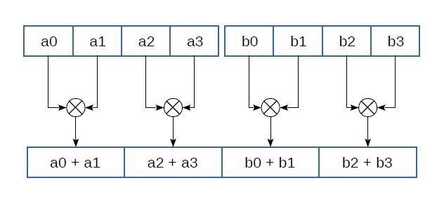
Figure 3: Horizontal addition
The SSE3 and SSSE3 instruction sets introduce instructions for horizontal addition (Fig. 3): _mm_hadd_ps(__m128 a, __m128 b), _mm_hadd_pd(__m128d a, __m128d b), _mm_hadd_epi16(__m128i a, __m128i b), and _mm_hadd_epi32(__m128i a, __m128i b). With horizontal addition, the adjacent elements of the same register are added together. Horizontal subtraction instructions are also provided (_mm_hsub_ps etc.) that subtract numbers in the same way. Similar instructions implementing pairwise addition (e.g. vpaddq_s16(int16x8_t a, int16x8_t b)) exist among the ARM NEON instructions.
Generally, with integer multiplication, the bit depth of the product is equal to sum of bit depths of multipliers. Thus, multiplying 16-bit elements of one register by the corresponding elements of another will, in the general case, yield 32-bit products that will require two registers instead of one to accommodate.
The _mm_mullo_epi16(__m128i a, __m128i b) instruction multiplies 16-bit elements of the registers a and b, writing the least significant 16 bits of the 32-bit product into the target register. Its counterpart _mm_mulhi_epi16(__m128i a, __m128i b) writes the most significant 16 bits of the product into the target register. The results produced by these instructions can be combined into 32-bit products using the _mm_unpacklo_epi16 and _mm_unpackhi_epi16 instructions that we will discuss below. Of course, if the multipliers are small enough, _mm_mullo_epi16 alone will suffice.
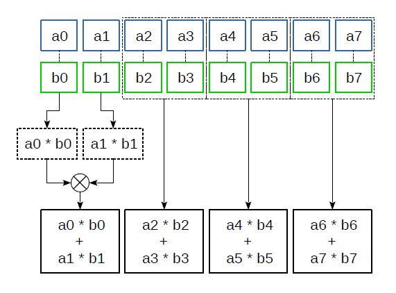
Figure 4: The _mm_madd_epi16 instruction
The _mm_madd_epi16(__m128i a, __m128i b) instruction multiplies 16-bit elements of the registers a and b and then adds together the resulting adjacent 32-bit products (Fig. 4). This instruction has proved especially useful for implementing various filters, discrete cosine transforms, and other transforms where many combined multiplications and additions are needed: it converts the products into the convenient 32-bit format right away and reduces the number of additions required.
ARM NEON has quite a diverse set of multiplication instructions. For example, it provides instructions that increase the product size (like vmull_s16) and those that do not, and it has instructions that multiply a vector by a scalar (such as vmul_n_f32). There is no instruction similar to _mm_madd_epi16 in NEON; instead, multiply-and-accumulate instructions are provided that work according to the formula $\displaystyle a_{i} =a_{i} +( b_{i} c_{i}) ,\ i=1..n $ . Instructions like this also exist in the x86 architecture (the FMA instruction set), but only for floating-point numbers.
As for integer vector division, it is not implemented on x86 or ARM.
Permutation and Interleaving
The processor instructions of the type discussed below do not have scalar counterparts. When they are executed, no new values are produced. Instead, either the data is permuted within the register, or the data from several source registers is written into the target register in a specific order. These instructions do not look very useful at first glance but are, in fact, extremely important. Many algorithms cannot be implemented efficiently without them.
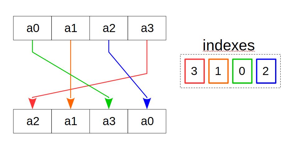
Figure 5: Copying by mask
Several x86 and ARM vector instructions implement copying by mask (Fig. 5). Consider having a source array, a target array, and an index array identical in size to the target, where each element in the index array corresponds to a target array element. The value of an index array element points to the source array element that is to be copied to the corresponding target array element. By specifying different indexes, all kinds of element permutations and duplications can be implemented.
Vector instructions use vector registers or their combinations as the source and target arrays. The index array can be a vector register or an integer constant with bit groups corresponding to the target register elements and coding the source register elements.
One of the instructions that implement copying by mask is the SSE2 _mm_shuffle_epi32(__m128i a, const int im) instruction that copies the selected 32-bit elements of the source register into the target register. The index array is the second operand, an integer constant that specifies the copy mask. This instruction is typically used with the standard macro _MM_SHUFFLE that offers a more intuitive way to specify the copy mask. For example, when executing
a = _mm_shuffle_epi32(b,_MM_SHUFFLE(0,1,2,3));
the 32-bit elements of b are written into the a register in reverse order. And when executing
a = _mm_shuffle_epi32(b,_MM_SHUFFLE(2,2,2,2));
the same value, namely the third element of the b register, is written into all elements of the a register.
The _mm_shufflelo_epi16 and _mm_shufflehi_epi16 instructions work in a similar fashion, but copy the selected 16-bit elements from the least significant and, respectively, the most significant half of the register and write the other half into the target register as is. As an example, we will show how these instructions can be used along with _mm_shuffle_epi32 to arrange the 16-bit elements of a 128-bit register in the reverse order in only three operations. Here is how it is done:
// a: a0 a1 a2 a3 a4 a5 a6 a7
a = _mm_shuffle_epi32(a, _MM_SHUFFLE(1,0,3,2)); // a4 a5 a6 a7 a0 a1 a2 a3
a = _mm_shufflelo_epi16(a, _MM_SHUFFLE(0,1,2,3)); // a7 a6 a5 a4 a0 a1 a2 a3
a = _mm_shufflehi_epi16(a, _MM_SHUFFLE(0,1,2,3)); // a7 a6 a5 a4 a3 a2 a1 a0
First, the most and least significant halves of the register are swapped, and then the 16-bit elements of each half are arranged in the reverse order.
The _mm_shuffle_epi8(__m128i a, __m128i i) instruction from the SSSE3 set also performs copying by mask but operates in bytes. (However, this instruction uses the same register as the source and target, so it is more of a "permutation by mask".) The indices are specified by the byte values in the second register operand. This instruction allows much more diverse permutations than the instructions discussed earlier, making it possible to simplify and speed up the computations in many cases. Thus, the entire above example can be reimplemented as a single instruction:
a = _mm_shuffle_epi8(a, i);For this, the bytes of the i register should have the following values (starting from the least significant byte): 4,15,12,13,10,11,8,9,6,7,4,5,2,3,0,1
In ARM NEON, copying by mask is implemented using several instructions that work with one source register (e.g., vtbl1_s8 (int8x8_t a, int8x8_t idx)) or a group of registers (e.g., vtbl4_u8(uint8x8x4_t a, uint8x8_t idx)). The vqtbl1q_u8(uint8x16_t t, uint8x16_t idx) instruction is similar to _mm_shuffle_epi8.
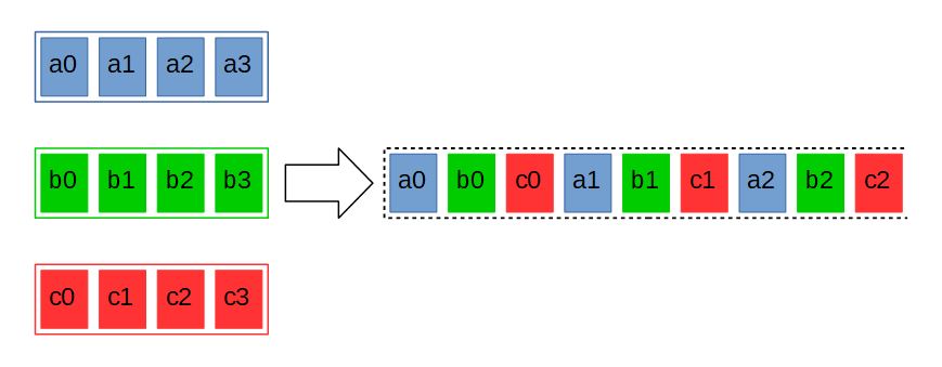
Figure 6: Shuffling
Another operation implemented using vector instructions is interleaving. Consider the following arrays: $\displaystyle A $ with the elements $\displaystyle a_{0} ,a_{1} ,...,a_{n} $, $\displaystyle B $ with the elements $\displaystyle b_{0} ,b_{1} ,...,b_{n} $, … and $\displaystyle Z $ with the elements $\displaystyle z_{0} ,z_{1} ,...,z_{n} $. When shuffled, the elements of these arrays are combined into one array in the following order: $\displaystyle a_{0} ,b_{0} ...,z_{0} ,a_{1} ,b_{1} ,...,z_{1} ,...,a_{n} ,b_{n} ,...,z_{n} $ (Fig. 6). The corresponding vector instructions also use registers — only two of them — as the source arrays. Obviously, as this operation does not change the size of data, there should also be two target registers.
Vector instructions on x86 can have only one target register, therefore the shuffling instructions process only half of the input data. Thus, _mm_unpacklo_epi16(__m128i a, __m128i b) shuffles the 16-bit elements of the least significant halves of the a and b registers, and its _mm_unpackhi_epi16(__m128i a, __m128i b) counterpart does the same with the most significant halves. 8-, 32-, and 64-bit instructions work similarly. The _mm_unpacklo_epi64 and _mm_unpackhi_epi64 instructions essentially combine the least and, respectively, most significant 64 bits of the two registers. Paired instructions are often used together.
Similar instructions exist in ARM NEON (the VZIP instruction family). Some of them use two target registers instead of one and thus process the entirety of the input data. There are also instructions that work in reverse (VUZP), for which there are no equivalents on x86.
The _mm_alignr_epi8(__m128i a, _m128i b, int imm) instruction copies the bytes of the source register b into the target register, starting from the selected byte imm, and copies the rest from the register a, starting from the least significant byte. Let the bytes of the a register have the values a0..a15, and the bytes of the b register have the values b0..b15. Then, when executing
a = _mm_alignr_epi8(a, b, 5);
the following bytes will be written into the a register: b5, b6, b7, b8, b9, b10, b11, b12, b13, b14, b15, a0, a1, a2, a3, a4. ARM NEON provides instructions of this kind that work with elements of specific size instead of bytes [3].
AVX and AXV2 instructions
The further development of x86 vector instructions is marked by the advent of 256-bit AVX and AVX2 instructions. What do these instructions offer to developers?
First of all, instead of eight (or sixteen) 128-bit XMM registers, there are sixteen 256-bit registers, YMM0–YMM15, in which the least significant 128 bits are the XMM vector registers. Unlike SSE, these instructions take three, not two register operands: two source registers and one target register. The contents of the source registers are not lost after executing an instruction.
Almost all operations implemented in the earlier SSE–SSE4.2 instruction sets are present in AVX/AVX2, most importantly the arithmetic ones. There are instructions that are fully analogous to _mm_add_epi32, _mm_madd_epi16, _mm_sub_ps, _mm_slli_epi16 and many others, but work twice as fast.
AVX/AVX2 have no exact equivalents for _mm_loadl_epi64 and _mm_cvtsi32_si128 (and the corresponding output instructions). Instead, the _mm256_maskload_epi32 and _mm256_maskload_epi64 instructions are introduced that load the required number of 32- and 64-bit values from the RAM using a bit mask.
New instructions such as _mm256_gather_epi32, _mm256_gather_epi64, and their floating-point equivalents have been added that load data in blocks using the start address and block offsets as opposed to a continuous array. These are especially useful when the desired data is not stored contiguously in the RAM, and many operations are needed to retrieve and combine it.
AVX2 has data interleaving and permutation instructions, such as _mm256_shuffle_epi32 and _mm256_alignr_epi8. They have a unique property that differentiates them from the rest of the AVX/AVX2 instructions. For example, the regular arithmetic instructions treat the YMM register as a 256-bit array. In contrast, these instructions treat YMM as two 128-bit registers and perform operations on them in exactly the same way as the corresponding SSE instruction.
Consider a register with the following 32-bit elements: A0, A1, A2, A3, A4, A5, A6, A7. Then, after executing
a = _mm256_shuffle_epi32(a, _M_SHUFFLE(0,1,2,3));
the register contents change to A3, A2, A1, A0, A7, A6, A5, A4.
Other instructions, such as _mm256_unpacklo_epi16, _mm256_shuffle_epi8, and _mm256_alignr_epi8, work in a similar fashion.
New permutation and interleaving instructions have also been added in AVX2. For instance, _mm256_permute4x64_epi64(__m256i, int imm) permutes 64-bit register elements similarly to how _mm_shuffle_epi32 permutes 32-bit elements.
Where do I get information on vector instructions?
First, visit the official websites of microprocessor vendors. Intel has an online reference where you can find a comprehensive description of intrinsics from all instruction sets. A similar reference exists for ARM CPUs.
If you would like to learn about the practical use of vector instructions, refer to the free-software implementations of audio and video codecs. Projects such as FFmpeg, VP9, and OpenHEVC use vector instructions, and the source code of these projects provides examples of their use.
Sources
- https://software.intel.com/sites/landingpage/IntrinsicsGuide
- https://developer.arm.com/architectures/instruction-sets/intrinsics
- https://community.arm.com/arm-community-blogs/b/architectures-and-processors-blog/posts/coding-for-neon---part-5-rearranging-vectors
February 1, 2022
Read more:
Chapter 1. Video encoding in simple terms
Chapter 2. Inter-frame prediction (Inter) in HEVC
Chapter 3. Spatial (Intra) prediction in HEVC
Chapter 4. Motion compensation in HEVC
Chapter 5. Post-processing in HEVC
Chapter 6. Context-adaptive binary arithmetic coding. Part 1
Chapter 7. Context-adaptive binary arithmetic coding. Part 2
Chapter 8. Context-adaptive binary arithmetic coding. Part 3
Chapter 9. Context-adaptive binary arithmetic coding. Part 4
Chapter 10. Context-adaptive binary arithmetic coding. Part 5
Chapter 11. DCT: brief overview
 Author
Dmitry Farafonov
An Elecard engineer. He has been working with optimization of audio and video codecs, as well as programs for processing audio and video signals since 2015.