CHAPTER 9

Binarization procedure in detail for the special case when the coding is performed using intra-prediction only.
Before we proceed to exploring the meaning of the remaining two words in the name of the entropy encoder used in HEVC (Context Adaptive Binary Arithmetic Coding; the words are presented in bold here), we need to finish discussing the word “Binary”. Let us return to the flow diagram of the coding algorithms shown in Figure 1 of Chapter 6. The information describing all decisions made during the coding of each block shown in the diagram is sent to the input of the entropy encoder. Most of this information is represented as integer numbers and not as bins that can only take values of 0 and 1. Of course, any integer number can be represented in binary to obtain a stream of bins at the input of the entropy encoder. However, this approach means that the probabilities of encountering zeros and ones in the binary message will be virtually equal, and therefore the data compression ratio in the arithmetic encoder will be close to zero. In other words, the number of bits in the encoded message after arithmetic coding will be no less than the number of bins at the encoder input. Because of that, there is a special procedure in HEVC called binarization that is applied to all numeric information sent to the input of the arithmetic encoder. This procedure converts all numeric values that describe the process of coding a certain image block to a set of binary bins. Let us consider this binarization procedure in detail for the special case when the coding is performed using intra-prediction only.
Remember that a video frame is coded in HEVC on a block-by-block basis, left-to-right and top-to-bottom. The coding blocks called LCUs are non-overlapping square areas that cover the whole image uniformly. Each LCU can be divided during coding into 4 square sub-blocks called CUs, each of which can, in turn, be divided into 4 smaller CUs. As a result of this division, the initial $\displaystyle 2^{M}$-sized LCU is represented as a quadtree called CTU. The maximum quadtree depth is a parameter of the encoding system. In addition, a minimum CU size of 8 is specified in the standard.
At the next coding step, spatial coding is performed for all CUs that are the “leaves” of the quadtree. The area for which the prediction is made is called a prediction unit (PU). Two cases are possible here. A CU can contain one PU identical in size to the CU or 4 square PUs of half the size. The latter case is only possible if the CU is located at the maximum allowed quadtree depth. The prediction itself for each PU area can be performed using one of 35 methods specified in the standard. Predicting the values of the luminance and color-difference components representing each image pixel in the area under consideration is done separately. The method used to predict the color-difference components can be different from that used to predict the luminance component. The predicted values are subtracted from the sample component values of the image being coded, forming a two-dimensional (2D) residual signal.
At the next coding step, a 2D spectral transform is applied on a block-by-block basis to the samples of this residual signal obtained from the spatial prediction step for the whole CU. The residual signal blocks subjected to spectral transformation are called TUs. The top-level TUs are identical in size to the containing CU. TUs can be divided during coding into 4 square sub-blocks of half the size. Each of these sub-blocks can, in turn, be divided into smaller ones. The result is a quadtree, and its “leaves” are the residual signal blocks to which the spectral transform is to be applied. The minimum TU size is specified in the standard as 4 and the maximum as 32. The spectral samples obtained as a result of the transform are quantized. The quantization step Δ is determined by the value of the quantization parameter Qp: $\displaystyle \Delta =2^{\frac{Q_{p} -4}{6}}$.
All values that describe the exact partitioning of the LCU into CUs, PUs and TUs during coding, the prediction mode chosen for each PU, the values obtained by quantizing the residual signal samples, etc. are called syntactic elements. The set of syntactic elements related to the current CU fully describes the choices made in the course of encoding the image in this block. This is the set that undergoes binarization before entropy encoding, a procedure whereby the value of each syntactic element is mapped into a set of binary characters, or bins. Presented below is a short list of the syntactic element types used to describe the coded image in HEVC using spatial prediction, as well as their associated binarization algorithms. The syntactic element names in this list are identical to those used in the H.265/HEVC specification.
The partitioning of an LCU into smaller CUs, i.e. the structure of the CU quadtree, is indicated in the stream using the split_cu_flag syntactic element. It can take two values: 0 if the current CU is not divided into smaller blocks, and 1 otherwise. The binary split_cu_flag value is sent to the input of the entropy encoder directly, skipping the binarization procedure.
The next syntactic element, part_mode, is present in the CU description if the maximum allowed partition depth has been achieved when constructing the quadtree. The part_mode element can only take two values. If part_mode = 1, the sizes of PU are CU identical. If part_mode = 0, the CU contains 4 square PUs of half the size. The binarization procedure for the values of this syntactic elements amounts to inverting its binary value.
Three syntactic elements are used to describe the spatial prediction mode (one of the 35 possible) used for the pixels of the luminance component of a PU: prev_intra_luma_pred_flag, mpm_idx and rem_intra_luma_pred_mode. The binary syntactic element prev_intra_luma_pred_flag has a value of 1 if the prediction mode number is to be computed from the mode numbers of the adjacent PUs (the adjacent PUs are the two PUs located next to the given PU on the left and top). There are three possible resulting values. The choice from these three values is indicated by the syntactic element mpm_idx that can take the values of 0, 1, and 2. If prev_intra_luma_pred_flag = 0, the spatial prediction mode number is neither of the three computed values. In this case, one of the 32 remaining prediction modes is chosen using a 5-bit syntactic element called rem_intra_luma_pred_mode.
The binary value prev_intra_luma_pred_flag is not binarized. The value mpm_idx = 0 is binarized into a single zero bin. The value mpm_idx = 1 is binarized into a two-bin sequence 10. The value mpm_idx = 2 is binarized into a two-bin sequence 11.
The binarization of rem_intra_luma_pred_mode maps its value into a 5-bin sequence giving a binary representation of the syntactic element’s value.
The prediction mode number for the color-difference components of a PU is indicated in the stream by the syntactic element intra_chroma_pred_mode that can take values from 0 to 4. If intra_chroma_pred_mode = 4, the prediction mode is identical to that of the luminance component. For the remaining four possible values, the corresponding prediction mode numbers are tabulated in the HEVC specification. The value intra_chroma_pred_mode = 4 is binarized as a single zero-valued bin. All the other values of intra_chroma_pred_mode are mapped by the binarization procedure into a sequence of 3 bins, the first of which is always 1, and the remaining two are a binary representation of the intra_chroma_pred_mode value.
The partitioning of the CU into square TUs, i.e. the structure of the TU quadtree, is indicated in the stream by the syntactic element split_transform_flag. If this element has a value of 0, the residual signal block subjected to spectral transformation is identical in size to the CU. Otherwise the TU is divided into 4 square blocks of half the size. The binary value split_transform_flag is not binarized.
The three syntactic elements cbf_cb, cbf_cr, and cbf_luma indicate whether the TU contains non-zero spectral sample values for the color-difference and luminance components of the residual signal. The values of these syntactic elements do not require binarization.
If any of the flags cbf_cb, cbf_cr, or cbf_luma are non-zero, the stream contains a description of the corresponding block of spectral samples. This description is implemented using eight different syntactic elements: last_sig_coeff_x, last_sig_coeff_y, coded_sub_block_flag, sig_coeff_flag, coeff_abs_level_greater1_flag, coeff_abs_level_greater2_flag, coeff_sign_flag, coeff_abs_level_remaining. The description of a TU starts with two syntactic elements, last_sig_coeff_x and last_sig_coeff_y. Their values are determined by the coordinates (x, y) of the last non-zero spectral sample in the TU for the given sample traversal order. When being traversed, the TU is divided into $\displaystyle 4\times 4$-sized sub-blocks. The traversal order for the sub-blocks within a TU and the coefficients inside each sub-block is identical. For $\displaystyle 4\times 4$ and $\displaystyle 8\times 8$ TUs, three traversal modes are possible: diagonal, horizontal, and vertical. The choice between them is determined by the prediction mode number. For larger TUs, only diagonal traversal is possible. The three traversal modes for a $\displaystyle 8\times 8$ TU are illustrated in Figure 1.
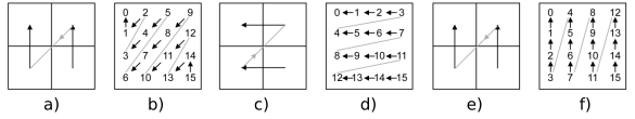
Figure 1. Three traversal modes for $\displaystyle 4\times 4$ blocks in a $\displaystyle 8\times 8$ TU and the coefficients inside each $\displaystyle 4\times 4$ block. Diagonal traversal order: (a) for blocks, (b) for coefficients. Horizontal traversal order: (c) for blocks, (d) for coefficients. Vertical traversal order: (e) for blocks, (f) for coefficients.
The further description of the TU is done by sub-block in the order specified by the traversal direction. The sub-block that contains the position (last_sig_coeff_x, last_sig_coeff_y) is described first and the one that contains the sample coordinates (0,0) is described last. Each sub-block’s description starts with the syntactic element coded_sub_block_flag. This element has a value of 1 if the sub-block contains non-zero spectral coefficients, otherwise coded_sub_block_flag is defined as zero, and this concludes the description of the sub-block.
For each of the sub-blocks that contain non-zero values, the description continues with a set of sig_coeff_flag syntactic elements. This element has a value of 1 if there is a non-zero spectral coefficient inside the sub-block, otherwise it is 0. The order of accessing the spectral coefficients inside the sub-block is determined by the traversal direction. A further description is only carried out for the positions where sig_coeff_flag = 1. For these positions, the description continues with a set of coeff_abs_level_greater1_flag syntactic elements that have a value of 1 if the absolute value of the corresponding spectral element is greater than 1 and are zero otherwise. No more than 8 syntactic elements of this type are generated for each sub-block. The order of generation is determined by the traversal direction. The next syntactic element, coeff_abs_level_greater2_flag, indicates the position of the first (in the traversal order) spectral sample with an absolute value that exceeds 2. The description of the spectral coefficient sub-block is continued with a sequence of coeff_sign_flag syntactic elements that indicate the sign (positive or negative) of each non-zero spectral sample, i.e. only those samples for which sig_coeff_flag = 1. For positive samples, coeff_sign_flag is set to 0, and for negative samples it is set to 1. Each sub-block’s description is concluded with a set of coeff_abs_level_remaining syntactic element values. The values of the generated syntactic elements are determined by the difference
coeff_abs_level_remaining = |W| - 1 - coeff_abs_level_greater1_flag - coeff_abs_level_greater2_flag,
where $\displaystyle W$ is the spectral element value. These values are present in the sub-block description only for those positions where sig_coeff_flag = 1 and the generated value of coeff_abs_level_remaining is not zero. An example of the description of a spectral coefficient sub-block (Figure 2) is shown in Table 1 (this example is taken from the book “High Efficiency Video Coding: Coding Tools and Specification” by M. Wien).
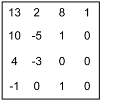
Figure 2. Example block of quantized spectral coefficients
Table 1
Syntactic element values in the block description (Figure 2)
| Coefficient values in the traversal order | 1 | 0 | 0 | 0 | 1 | 1 | -3 | -1 | 8 | -5 | 4 | 2 | 10 | 13 |
| sig_coeff_flag | - | 0 | 0 | 0 | 1 | 1 | 1 | 1 | 1 | 1 | 1 | 1 | 1 | 1 |
| coeff_abs_level_greater1_flag | 0 | - | - | - | 0 | 0 | 1 | 0 | 1 | 1 | 1 | 1 | - | - |
| coeff_abs_level_greater2_flag | - | - | - | - | - | - | 1 | - | - | - | - | - | - | - |
| coeff_sign_flag | 0 | - | - | - | 0 | 0 | 1 | 1 | 0 | 1 | 0 | 0 | 0 | 0 |
| coeff_abs_level_remaining | - | - | - | - | - | - | 1 | - | 7 | 4 | 3 | 1 | 10 | 13 |
The values of last_sig_coeff_x and last_sig_coeff_y are binarized into bin sequences that consist of two parts, the prefix and the suffix. The rules of binarization are illustrated in Table 2. In the prefix string, the zero bin shown in parentheses in the second table column is omitted if the value to be binarized is equal to $\displaystyle nT-1$, where $\displaystyle nT$ is the TU size. The quantities $\displaystyle x_{i}$ that make up the suffix bin string are the values of the i-th bits of the binary representation of the number to be binarized.
Table 2
Binarization of last_sig_coeff_x and last_sig_coeff_y
| Value to be binarized | Prefix bin string | Suffix bin string |
| 0 | 0 | |
| 1 | 10 | |
| 2 | 110 | |
| 3 | 111(0) | |
| 4, 5 | 11110 | $\displaystyle x_{0}$ |
| 6, 7 | 11111(0) | $\displaystyle x_{0}$ |
| 8, ..., 11 | 1111110 | $\displaystyle x_{1} x_{0}$ |
| 12, ..., 15 | 1111111(0) | $\displaystyle x_{1} x_{0}$ |
| 16, ..., 23 | 11111111 | $\displaystyle 0\ x_{2} x_{1} x_{0}$ |
| 24, ..., 31 | 11111111 | $\displaystyle1\ x_{2} x_{1} x_{0}$ |
The values of the single-bit syntactic elements used for describing a sub-block of spectral coefficients (coded_sub_block_flag, sig_coeff_flag, coeff_abs_level_greater1_flag, coeff_abs_level_greater2_flag, coeff_sign_flag) do not require binarization.
The values of the syntactic element coeff_abs_level_remaining are binarized into two bin sequences, the prefix and the suffix. The binarization procedure is parameterized. The value of the binarization parameter k is determined from the values of the previous (binarized earlier) values of the syntactic elements coeff_abs_level_remaining in this sub-block. Examples of binarization results for two values of k are shown in Table 3 (taken from the book “High Efficiency Video Coding: Coding Tools and Specification” by M. Wien). The value to be binarized is denoted in Table 3 as $\displaystyle Z$ and the bit values of the binary representation of $\displaystyle Z$ as $\displaystyle x_{i}$. The prefix bin sequence is shown in bold in the table.
Table 3
Examples of coeff_abs_level_remaining binarization
| $\displaystyle Z$ | Binarization result for $\displaystyle k=0$ | $\displaystyle Z$ | Binarization result for $\displaystyle k=1$ |
| 0 | $\displaystyle 0$ | 0, 1 | $\displaystyle0\ x_{0}$ |
| 1 | $\displaystyle 10$ | 2, 3 | $\displaystyle10\ x_{0}$ |
| 2 | $\displaystyle 110$ | 4, 5 | $\displaystyle110\ x_{0}$ |
| 3 | $\displaystyle 1110$ | 6, 7 | $\displaystyle1110\ x_{0}$ |
| 4, 5 | $\displaystyle11110\ x_{0}$ | 8, ..., 11 | $\displaystyle11110\ x_{1} x_{0}$ |
| 6, ..., 9 | $\displaystyle111110\ x_{1} x_{0}$ | 12, ..., 19 | $\displaystyle111110\ x_{2} x_{1} x_{0}$ |
| 10, ..., 17 | $\displaystyle1111110\ x_{2} x_{1} x_{0}$ | 20, ..., 35 | $\displaystyle1111110\ x_{3} x_{2} x_{1} x_{0}$ |
December 17, 2019
Read more:
Chapter 1. Video encoding in simple terms
Chapter 2. Inter-frame prediction (Inter) in HEVC
Chapter 3. Spatial (Intra) prediction in HEVC
Chapter 4. Motion compensation in HEVC
Chapter 5. Post-processing in HEVC
Chapter 6. Context-adaptive binary arithmetic coding. Part 1
Chapter 7. Context-adaptive binary arithmetic coding. Part 2
Chapter 8. Context-adaptive binary arithmetic coding. Part 3
Chapter 10. Context-adaptive binary arithmetic coding. Part 5
About the author:
Oleg Ponomarev, 16 years in video encoding and signal digital processing, expert in Statistical Radiophysics, Radio waves propagation. Assistant Professor, PhD at Tomsk State University, Radiophysics department. Head of Elecard Research Lab.