CHAPTER 8

How the binary nature of the coded information will change the encoding and decoding procedures.
The input character stream must be binary!
The name CABAC (Context Adaptive Binary Arithmetic Coding) itself implies that HEVC uses a binary version of arithmetic coding where the input message alphabet consists of only two characters, 0 and 1. In order to distinguish between the words used to denote the output stream bits that represent the coding result and the binary characters that represent the message being coded, the term “bins” is used to refer to these characters. Let us see what will change if we take into account the binary nature of the message being coded in the flow diagrams shown in Figures 2 to 4 of Chapter 7.
The first thing to note is that the EOF character that used to denote the end of the message is no longer part of the alphabet. The point where the message ends needs to be known at the time of decoding, otherwise the decoding procedure will continue even after the entire message has been decoded correctly. We will explore later how the end-of-message information is transmitted in HEVC and will just note for now that a procedure for transmitting this information needs to be implemented.
What else will change if there are only two different characters in the message to be coded? The array $\displaystyle P\\$ where cumulative character probabilities are stored will only contain three values: $\displaystyle P=\{0,P_{MPS} ,1\}$. Here, $\displaystyle P_{MPS}$ is the probability of the more probable character occurring in the message (if we exclude the EOF character from our 20-character message {b, a, b, b, b, b, b, b, b, b, a, b, b, b, b, b, b, b, b, EOF}, the message will become 19 characters long, and the probability of the more probable character “b” will be equal to $\displaystyle \frac{17}{19}$). This means that the current interval $\displaystyle [ L,H)$ will now be split into two parts at each iteration during coding. The length of the larger part is determined by the probability $\displaystyle P_{MPS}$ and the length of the smaller part by the probability $\displaystyle P_{LPS} =1-P_{MPS}$. The array $\displaystyle P$ has thus basically degenerated into a single number. This number could be $\displaystyle P_{MPS}$ or it could just as well be $\displaystyle P_{LPS}$.
Until now, the position on the number axis of the interval to be split during coding was characterized by the position of the interval’s endpoints $\displaystyle L$ and $\displaystyle H$. Obviously, we can also describe the current state of the arithmetic coding procedure (the position of the interval on the number axis) using the numbers $\displaystyle L$ and $\displaystyle R$, where $\displaystyle R$ is the interval length. This is the description used in HEVC.
Now let us denote the number that characterizes the ratio between the interval parts when split iteratively as $\displaystyle P_{LPS}$. Using the HEVC standard notation, let $\displaystyle valMPS$ be the value (0 or 1) of the most probable bin in the sequence to be coded, $\displaystyle binVal$ the value of the bin currently being coded, $\displaystyle L$ the position of the left interval endpoint (as before), and $\displaystyle R$ the current interval length. If the value of the currently coded bin is equal to $\displaystyle valMPS$, the new values of $\displaystyle L$ and $\displaystyle R$ can be calculated from their current values and $\displaystyle P_{LPS}$ as (Figure 1):
\begin{array}{l}R=R( 1-P_{LPS}) =R-R\cdotp P_{LPS} ,\ and\end{array}
\begin{array}{l}L=L.\end{array}
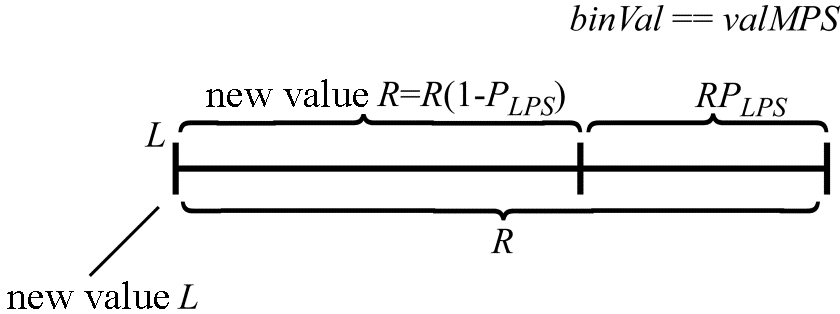
Figure 1. Calculating $\displaystyle L\\$ and $\displaystyle R\\$ when $\displaystyle binVal\equiv valMPS$
If the value of the currently coded bin is not equal to $\displaystyle valMPS\\$, the new values of $\displaystyle L\\$ and $\displaystyle R\\$ will be determined by the following expressions (Figure 2):
\begin{array}{l}R=R\cdotp P_{LPS},\end{array}
\begin{array}{l}L=L+R( 1-P_{LPS}).\end{array}
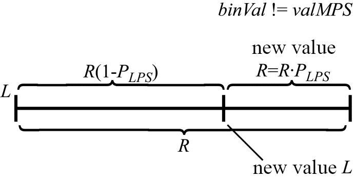
Figure 2. Calculating $\displaystyle L$ and $\displaystyle R$ when $\displaystyle binVal!=valMPS$
The result is a somewhat updated flow diagram (Figure 3), now describing binary arithmetic coding.
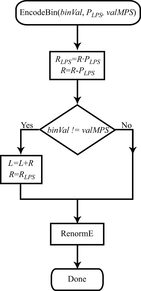
Figure 3. Flow diagram for the bin coding procedure
Although the renormalization procedure could be left unmodified for binary coding, some small modifications to it can simplify the algorithm somewhat and save computational effort. Using the new notation of $\displaystyle L$ and $\displaystyle R$, the renormalization procedure is executed in a loop while $\displaystyle R< \frac{1}{2} $. If at the same time $\displaystyle L+R< \frac{1}{2}$, the value of the coded bit is defined and equal to 0. If $\displaystyle L >\frac{1}{2}$, the coded bit has a value of 1 (we just state it here for simplicity; the procedure is described in detail in Figure 2 of Part 2 and the associated explanatory text). Clearly, the values of the coded bits will also be fully defined when $\displaystyle R< \frac{1}{4}$. If at the same time $\displaystyle L< \frac{1}{4}$, the current interval is fully contained inside the range $\displaystyle \left[ 0,\frac{1}{2}\right] $, and thus the value of the coded bit is 0. If $\displaystyle R< \frac{1}{4}$ but $\displaystyle L\geqslant \frac{1}{2}$, the current interval is fully contained inside the range $\displaystyle \left[\frac{1}{2} ,1\right] $, and the coded bit has a value of 1. The flow diagram for the modified renormalization procedure for the coding is shown in Figure 4.
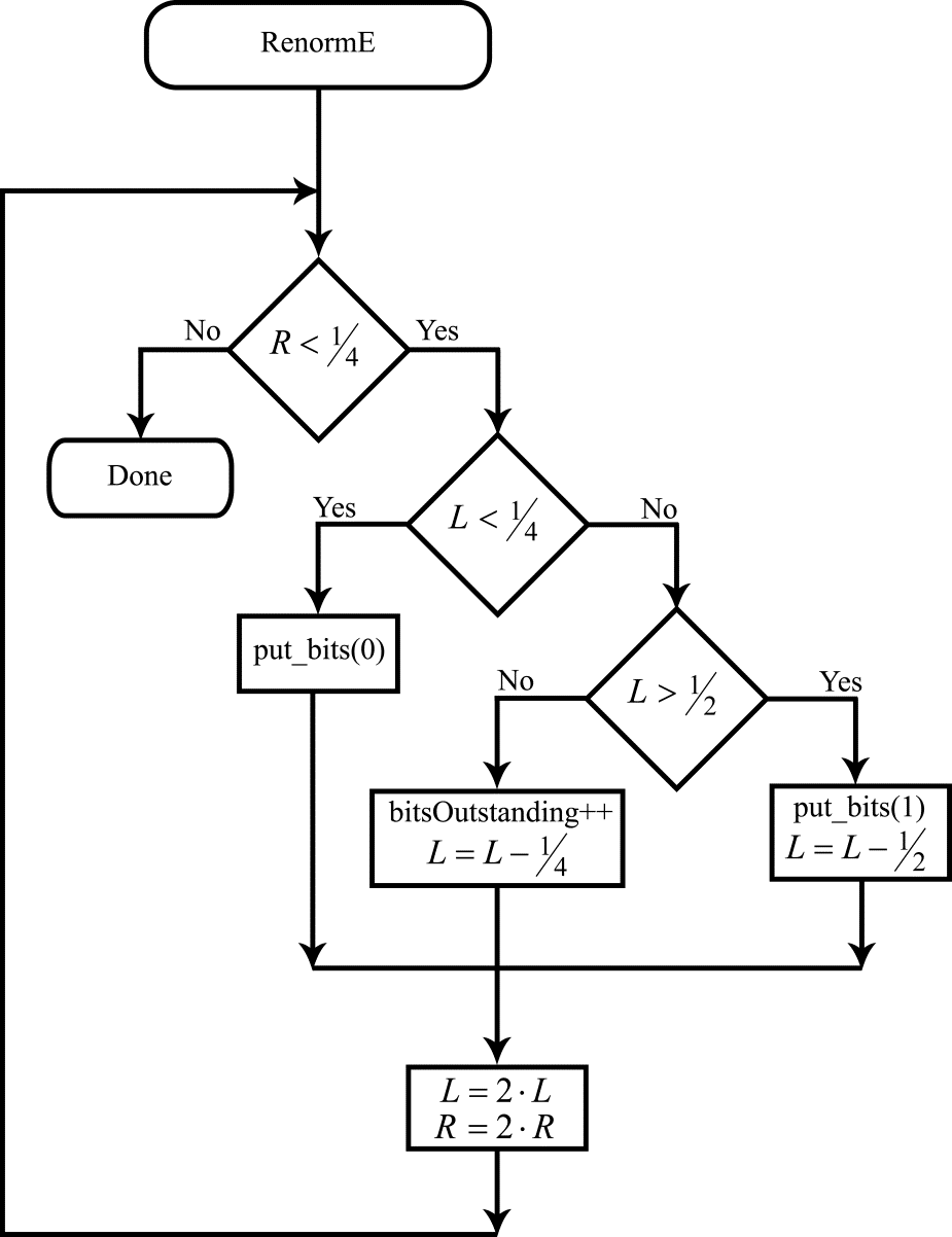
Figure 4. Flow diagram for the renormalization algorithm for the coding
Let us now see how the binary nature of the coded information will change the decoding procedure. The procedure of arithmetic decoding in this case consists of splitting the current interval iteratively into two parts with lengths proportional to $\displaystyle 1-P_{LPS}$ and $\displaystyle P_{LPS}$. At each such iteration, a check is performed to see which of the two resulting intervals includes the binary number representing the encoded message. This becomes the current interval.
Let $\displaystyle ivlOffset$ be a variable that contains several bits of the encoded message (we use the HEVC notation for this variable here). As before, let us characterize the current interval by its left endpoint $\displaystyle L$ and the length $\displaystyle R$. The decoding procedure is illustrated in Figure 5 where two successive iterations are shown. At the first iteration, the number $\displaystyle ivlOffset$ (with its position inside the current interval shown by a circle) is located inside the interval
$\displaystyle [ L,L+R( 1-P_{LPS})]$. As a result, the decoded bin is equal to $\displaystyle valMPS$. At the second iteration, the number $\displaystyle ivlOffset$ is located inside the smaller interval, and the decoded bin is equal to $\displaystyle!valMPS$.
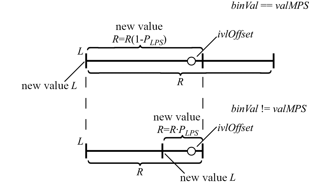
Figure 5. Interval splitting during decoding
It can be seen from the figure above that the choice of the interval at each iteration is determined by comparing the value of $\displaystyle ivlOffset$ with the right-hand endpoint of the interval $\displaystyle L+R\cdotp ( 1-P_{LPS})$. When $\displaystyle ivlOffset$ falls inside the larger interval that corresponds to the probability $\displaystyle P_{MPS}$, $\displaystyle R$ gets a new value of $\displaystyle R\cdotp ( 1-P_{LPS})$, and $\displaystyle L$ is left unchanged. When $\displaystyle ivl0ffset$ falls inside the smaller interval that corresponds to the probability $\displaystyle P_{LPS}$, the left interval endpoint is redefined as $\displaystyle L+R\cdotp ( 1-P_{LPS})$, and $\displaystyle R$ gets a new value of $\displaystyle R\cdotp P_{LPS}$. Note that in the second case, instead of modifying $\displaystyle L$ we can modify $\displaystyle ivlOffset$ by assigning it a value of $\displaystyle ivlOffset-R\cdotp ( 1-P_{LPS})$. What the value of $\displaystyle ivlOffset$ now characterizes is not the binary number itself that represents the encoded message but instead the position of this number relative to the left endpoint of the current interval. In that case, $\displaystyle L$ as such is no longer used in the decoding procedure. To decide which of the two intervals shall become the current one at each iteration, we just need to compare $\displaystyle ivlOffset$ with $\displaystyle R\cdotp ( 1-P_{LPS})$. The flow diagram for the decoding algorithm is shown in Figure 6.
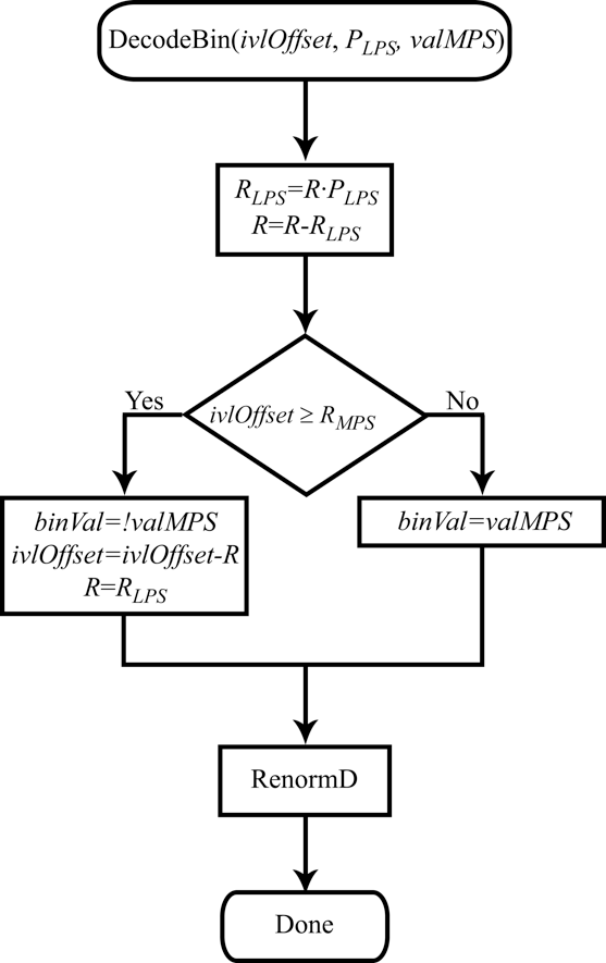
Figure 6. Flow diagram for the decoding algorithm
Redefining the meaning of $\displaystyle ivlOffset$ for binary coding also leads to a significant change (simplification) in the renormalization procedure. The renormalization procedure is invoked when the current interval length becomes less than $\displaystyle \frac{1}{4}$. Just as before, renormalization doubles the value of $\displaystyle R$. It is, however, no longer necessary to compute $\displaystyle L$. Since $\displaystyle ivlOffset$ is now the difference between the number representing the encoded message and the left endpoint of the current interval, the renormalization procedure can simply double the value of $\displaystyle ivlOffset$ unconditionally and then add a bit from the encoded message to the vacant bit position, thereby increasing the precision of the value $\displaystyle ivlOffset$. The flow diagram for the modified renormalization algorithm during binary decoding is shown in Figure 7.
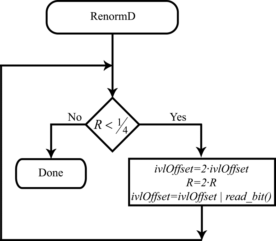
Figure 7. Flow diagram for the renormalization algorithm during decoding
This flow diagram calls a function called read_bit(), the purpose of which is evident from its name: the function reads the next bit from the bit stream representing the encoded message. It also uses the symbol “|” for bitwise OR operation from the C language.
December 10, 2019
Read more:
Chapter 1. Video encoding in simple terms
Chapter 2. Inter-frame prediction (Inter) in HEVC
Chapter 3. Spatial (Intra) prediction in HEVC
Chapter 4. Motion compensation in HEVC
Chapter 5. Post-processing in HEVC
Chapter 6. Context-adaptive binary arithmetic coding. Part 1
Chapter 7. Context-adaptive binary arithmetic coding. Part 2
Chapter 9. Context-adaptive binary arithmetic coding. Part 4
Chapter 10. Context-adaptive binary arithmetic coding. Part 5
About the author:
Oleg Ponomarev, 16 years in video encoding and signal digital processing, expert in Statistical Radiophysics, Radio waves propagation. Assistant Professor, PhD at Tomsk State University, Radiophysics department. Head of Elecard Research Lab.