CHAPTER 4

Motion vector prediction algorithms in HEVC: reference image information and motion vector prediction.
The HEVC standard implements all of the above ideas that provide the best inter-frame prediction “quality”. This involves the ability to specify the prediction vector with 1/4-pixel accuracy, use one- and bi-directional prediction, vary adaptively the shape and size of the image areas being predicted, create long (up to 15 elements) reference frame lists, and use motion vector prediction algorithms so that only information about the difference vectors (mvd) is added to the encoded stream. How is this all implemented? Let’s find out.
Reference image information
It is clear that to implement inter-prediction, the encoding and decoding systems must have a memory buffer to store the decoded images. This buffer is called a DPB (from Decoded Picture Buffer). Some images in DPB are “waiting” for their turn to be displayed on the screen (in the decoding system), while others stay in the buffer to enable inter-prediction when coding other video frames. The frames that are going to be used for inter-prediction have to be tagged in some way during coding, and the information about these tags must be added to the encoded video stream. There are two types of such tags in HEVC. The first is called short-term reference. It is used to tag those images in the DPB that can be used as inter-prediction reference frames for blocks in the current frame or in the two closest subsequent video frames (in the order of decoding). The second type of tag, called long-term reference, concerns those frames in DPB that can be used to predict image blocks in frames that are more than two frames away from the current one (again, in the order of decoding). All images in the DPB that are not tagged as short-term reference or long-term reference are considered unused for reference and cannot be used at a later time to perform inter-prediction. The information about these tags is added to the header of each frame in the encoded video stream. This information is called the Reference Picture Set (RPS).
Each frame in the encoded video stream has an identifier, or POC (from Picture Order Counter). In the most simplified interpretation, the POC value can be viewed as the ordinal number of the image in the video sequence*. The information from which the POC can be determined is put into the encoded stream for each image by the encoding system. Thus, all decoded images in the DPB have unique POC values. It is these values that are used to tag short-term reference and long-term reference video frames in the DBP.
*Note. In actual fact, each frame’s POC value is not unique in the entire video sequence. Usually, an encoded HEVC stream contains frames that have been coded using intra-frame prediction, or I-frames. Reference images are of course not needed to decode such frames. When all frames that follow such an I-frame in the video sequence are predicted (uni- or bi-directionally) using only those reference frames that are located after the I-frame, the POC value for this I-frame is set to zero. Therefore, the POC values are only unique within a group of video frames related to each other via P- or B-prediction. Note also that when I-frames are being decoded or encoded, all DPB content is tagged as unused for reference—in other words, the Reference Picture Set (RPS) is cleared.
First of all, information about the POC values of those frames that are to be tagged as short-term reference is added to the RPS description in the encoded stream. Since not all reference images that have made it into the RPS are used for predicting the current video frame, each POC value in the RPS description is appended with a flag (a single bit) which, if zero, indicates that this reference image is not used in the prediction of the current frame. Accordingly, if this flag has a value of 1, it indicates that this reference image is used for predicting the current video frame.
The information about the positions of the frames tagged as long-term reference forms a separate list in the RPS. This list contains POC values (the scenarios here can vary, but let us not labor the point), each of which is accompanied by the value of a single-bit flag. This flag serves the same purpose as the one for short-term reference. If it has a value of 1, it indicates that this reference image is used for predicting the current video frame.
The POC values for the frames in the DPB tagged as short-term reference or long-term reference are used to create reference picture lists during the preparation stage of inter-prediction. When uni-directional prediction (P-prediction) is to be performed, one such list is created called RefPicList0. For B-prediction, two lists are created: RefPicList0 and RefPicList1. Naturally, these lists are only formed from the POC values of those tagged frames in the DPB that have the flag in the RPS set to 1. The lengths of these lists are transmitted in the encoded stream. The POC values are added until the lists are full. Initially, the RefPicList0 list is populated with the POC values for the short-term reference frames that precede the current frame in the video sequence, i.e. those that have a POC value lower than the current frame’s POC. These frames are sorted by POC in descending order, meaning that the lowest index in the RefPicList0 list belongs to the short-term reference frame that has a POC value closest to the current frame’s POC but not exceeding it. If the list is not full after the addition, it then is consecutively populated with all short-term reference frames that have a POC value higher than the current frame’s POC. These frames are sorted in ascending order of POC value. Finally, if the list is still not full, it is populated with frames tagged in the RPS as long-term reference.
The RefPicList1 list is formed in a similar fashion, the only difference being that it is first populated with the short-term reference frames that have a POC value higher than the current frame’s POC. As before, these frames are sorted in ascending order of POC value. Next, the list is populated with the short-term reference frames that have a POC value lower than the current frame’s POC, sorted in descending order of POC value. At the final step, the RefPicList1 list is populated with the POC values of frames tagged as long-term reference.
The RefPicList0 and RefPicList1 lists thus formed make it possible to use the reference image indexes stored in these lists inside the encoded stream as pointers to a certain frame in the DPB that should be used for predicting the block being coded in the current video frame.
Motion vector prediction
In HEVC, the result of motion vector prediction for each block being encoded or decoded is a list of two motion vectors. For each block of the image being coded, the encoded video stream carries an index valued 0 or 1 that indicates which list element is to be used as the mvp.
The main idea in forming this list is that there is a high probability that the motion vector for the current block will bear little difference from the motion vectors for the adjacent blocks coded earlier, which can thus be used as a prediction. This simple idea is augmented by another one. The reference frame list is highly likely to contain a frame that differs slightly from the current one. Therefore, the motion vector for a block located in a frame from this list at the same or almost the same position as the block being coded may well serve as a good prediction. Overall, this list is formed using two motion vectors for the adjacent blocks CandA and CandB located in the current frame and a motion vector from the so-called co-located block that resides in one of the reference frames. The index of the reference frame that contains co-located blocks for all blocks of the current image is transmitted in the header part of the image being coded.
The list of two candidates is formed as follows. First, motion vectors for the blocks CandA and CandB are added to the list if they are both available (i.e. they exist and have already been coded), are coded in the inter-prediction mode, and differ from each other. If these blocks have identical motion vectors, only one vector is added to the list. If the list does not contain two elements after adding the motion vectors for the adjacent blocks CandA and CandB, the motion vector for the co-located block is added to it. If the list is still not fully populated, the empty positions are filled with zero motion vectors.
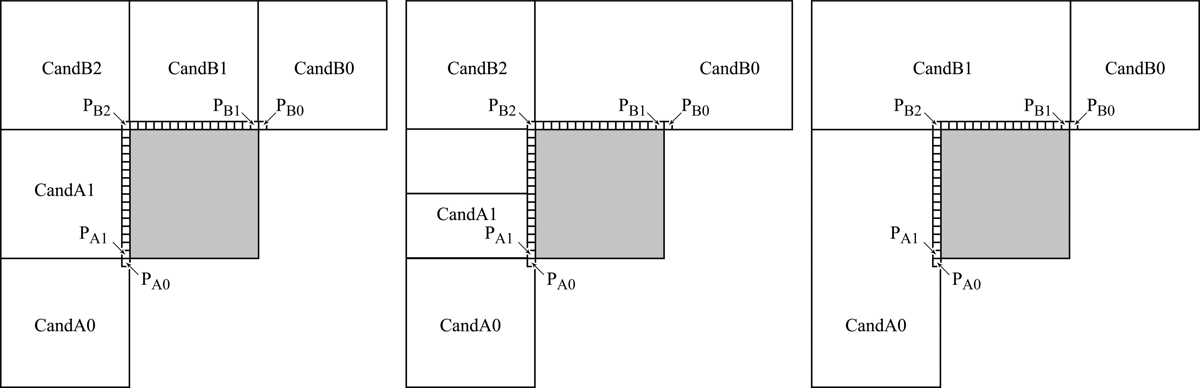
Figure 1.Examples of candidate block locations relative to the current block being coded (shown in gray color)
The CandA candidate block is selected from two blocks, CandA0 and CandA1, that are located to the left of the current one. As already mentioned, HEVC allows for adaptive division of video image into blocks for coding. As a result, there are many possible configurations of the blocks located to the left of the current block. Figure 1 shows several of these configurations. The choice between the blocks CandA0 and CandA1 is determined by the location of two pixels denoted as PA0 and PA1 in Figure 1. CandA0 is the image block that contains PA0, and CandA1 is the block that contains PA1.
The CandB candidate block is selected from three blocks, CandB0, CandB1 and CandB2. The choice is determined by the location of three pixels denoted as PB0, PB1, and PB2 in Figure 1. CandB0 is the block that contains PB0, CandB1 is the block that contains PB1, and CandB2 is the block that contains PB2.
To summarize, the first step of forming the list of two blocks {CandA, CandB} is to select one candidate from the blocks CandA0 and CandA1 and another candidate from the blocks CandB0, CandB1, and CandB2. The selection is performed in the numerical order of the candidate blocks. In other words, when the block CandA is being chosen, CandA0 is checked first, followed by CandA1. The check verifies that the following conditions are satisfied:
- The candidate block has already been coded, specifically in the inter-prediction mode.
- The candidate block has the same reference frame as the block to be coded.
If both conditions are satisfied, the candidate block is put into the {CandA, CandB} list in the corresponding position. For instance, if the block CandA0 has been coded in the inter-prediction mode and has the same reference frame as the block to be coded, it is put into the list as CandA. If none of the candidate blocks satisfy condition 2, the first candidate block that satisfies condition 1 is put into the list. In this case, to use the motion vector of that block as the mvp, it needs to be scaled according to the following equation:
\begin{array}{l} mvp=\frac{t_{b}}{t_{d}} \cdot mv \\\end{array}
where $\displaystyle t_{b} $ is the difference between the POC values of the frame to be coded and the reference frame of the block to be coded; $\displaystyle t_{d} $ is the difference between the POC values of the frame containing the block from the list and its reference frame; and $\displaystyle mv $ is the motion vector for the block from the list. The notation introduced here is illustrated in Figure 2.
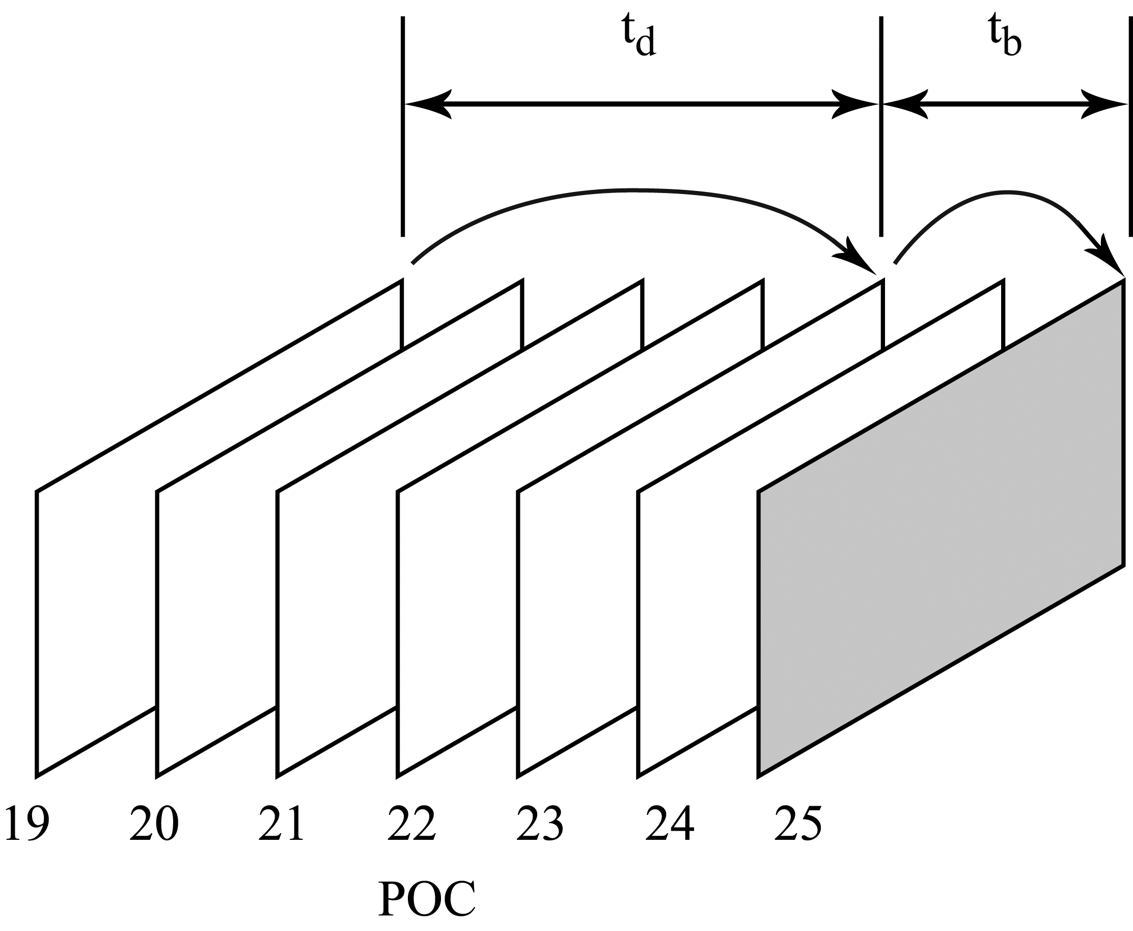
Figure 2. Notation used for scaling. The example shown in the figure has $\displaystyle t_{b} =25-23=2t_{d} =23-19=4 $
If none of the candidate blocks CandA0 and CandA1 satisfy condition 1, the first available block from the set of candidate blocks CandB0, CandB1, and CandB2 is put into the list as the CandA element.
As already mentioned, if the list {CandA, CandB} is still not fully populated after checking the spatial candidate blocks, the so-called co-located block is added to the list. This block is located in the reference frame whose number is carried in the header part of the frame being coded. The co-located block can be one of the two candidate blocks in the reference frame with coordinates relative to the block being coded defined as shown in Figure 3. If the candidate block containing the pixel C0 satisfies the conditions for use as the co-located block (i.e. it has been coded in the inter-prediction mode and belongs to the LCU with the same number as the block being coded), it is put in the first vacant position in the list {CandA, CandB}. Otherwise, the candidate block containing pixel С1 is put in this position — again, provided that it satisfies the conditions for use as the co-located block.
After adding the co-located block to the list {CandA, CandB}, the remaining empty positions in the list are filled with zero motion vectors.
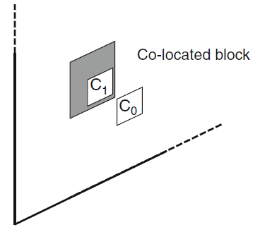
Figure 3. The position of the co-located block
February 12, 2019
Read more:
Chapter 1. Video encoding in simple terms
Chapter 2. Inter-frame prediction (Inter) in HEVC
Chapter 3. Spatial (Intra) prediction in HEVC
Chapter 5. Post-processing in HEVC
Chapter 6. Context-adaptive binary arithmetic coding. Part 1
Chapter 7. Context-adaptive binary arithmetic coding. Part 2
Chapter 8. Context-adaptive binary arithmetic coding. Part 3
Chapter 9. Context-adaptive binary arithmetic coding. Part 4
Chapter 10. Context-adaptive binary arithmetic coding. Part 5
About the author:
Oleg Ponomarev, 16 years in video encoding and signal digital processing, expert in Statistical Radiophysics, Radio waves propagation. Assistant Professor, PhD at Tomsk State University, Radiophysics department. Head of Elecard Research Lab.