CHAPTER 2

How to eliminate spatial or temporal redundancy: non-integer motion vectors, bi-directional prediction, adaptive selection of image block shape, size, and position during prediction, lists of frames to be used as reference block sources for motion compensation, motion vector prediction.
A key step in digital video data processing in hybrid block video encoding systems is eliminating spatial or temporal redundancy. To eliminate temporal redundancy, the coding system searches the previously encoded video images for the most similar image area (block) to the block currently being encoded. Once found, the samples (pixels) of this block are used as an estimate, or prediction, for the pixel values of the current block. The predicted samples are subtracted from the samples of the current block, resulting in a difference signal (residual). Obviously, this residual only contains information about the differences between the images in the current block and the predictive block. In case of a “good” prediction, the residual contains significantly less information than the block being encoded, which determines to a large extent the video data compression ratio during encoding. It is the residual signal information that, after some additional processing, is placed in the encoded stream; basically, it constitutes the result of encoding.
Other information is also added to the stream to allow a decoding system to make the prediction. What kind of information is it? First of all, some identifier is needed for the previously encoded video image (called the reference) in which the predictive block was found. The identifier should be accompanied by information about the coordinates of the predictive block inside the reference image. These coordinates are usually specified relative to the position of the block currently being encoded - in other words, as the current block’s offset from the predictive block. A set of horizontal and vertical offsets is thus called a motion vector. In essence, the motion vector shows how far the current block has shifted from the predictive block.
The basic decoding procedure is to find a reference image among the previously encoded images using its identifier, obtain the predictive block samples from this image based on the known coordinates, and add to them the residual signal values from the encoded stream. The result is a decoded image. Easy! This simple idea was first implemented back in 1988 during the development of the H.261 standard. In the course of the last 25 years, it was augmented with several others which made it possible to significantly reduce the amount of information required both to describe the residual signal and to identify the block on the reference image used for prediction. Here is a quick summary of these extensions.
Non-integer motion vectors
It is clear that in real-world video sequences, it often happens that the image of one frame is offset from the image in another (reference) frame by a non-integer number of samples. The introduction of non-integer motion vectors in this situation makes it possible to improve the “quality” of the prediction considerably. With non-integer offsets, interpolated (shifted relative to an integer position) reference block samples are used for prediction. The magnitude and direction of this shift are defined by the fractional parts of the horizontal and vertical motion vector components.
Bi-directional prediction
Bi-directional block prediction uses two reference blocks, each of which may reside in its own reference frame. The prediction for the block currently being encoded is formed as a half-sum of the sample values from both blocks. Most commonly, one of the reference frames comes from the part of the video sequence before the frame that contains the current block and the other comes from the part after the current frame. Since only previously encoded frames can be used as a reference, the introduction of bi-directional prediction makes it necessary to encode video frames in a different order from the one in which they appear in the video (see Figure 1). But what is the actual idea here? How does this bi-directional prediction—or bi-prediction, with blocks encoded in this way referred to as B-blocks and encoded frames containing these blocks as B-frames—bring improvement in the video data compression ratio and hence prediction “quality”? Consider several scenarios in which this improvement is clear.
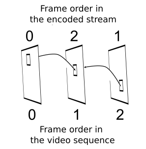
Fig 1. With bi-directional prediction, the order in which video frames are encoded or decoded can be different from their order in the video sequence
Scenario 1. Suppose that non-integer motion vectors in the encoding system can be specified with quarter-pixel accuracy. One reference frame precedes the frame currently being encoded in the video sequence, and the other comes after the current frame (see Figure 1). The current block is offset horizontally relative to the reference block in the first reference frame by –1/6 pixel. If it is also offset relative to the second reference block by 1/6 pixel along the same axis, then the arithmetic mean of the samples from the two blocks will be equivalent to a linear interpolation for calculating samples shifted by 1/6 pixel. Thus, bi-directional prediction in this case amounts to increasing the accuracy with which the motion vectors are specified. Of course, the above example is somewhat idealized. However, even when the fractional parts of the motion vectors are not equal in absolute value, averaging samples from the two blocks increases the “quality” of prediction. (Why are opposite-signed offsets used in the example? It is simply because one of the reference frames precedes the current frame and the other follows it. When objects in a frame are moving continuously, it is highly likely that the image in the current block will be offset in opposite directions relative to the first and second reference images.)
Scenario 2. Suppose that some object filmed by a video camera is rotated with time in a plane parallel to the video frame plane. Again, we have two reference frames here, one of which is recorded earlier than the frame currently being encoded and the other at a later point in time. It is clear that the image in the current block will be rotated with respect to the reference images by opposite-signed angles. If the angles are small, averaging the reference images will compensate (perhaps not completely) for this rotation, which will provide for better prediction “quality”.
Scenario 3. The image in the block being encoded does not move relative to the preceding or subsequent reference images. However, the illuminance in this area of the frame changes with time— for instance, the image gets darker. Clearly, in this case it is also possible to achieve a closer approximation of the image using bi-directional prediction.
In real-world video sequences, any combinations of the above scenarios are possible. It is clearly possible to come up with further examples where bi-directional prediction would bring obvious improvement.
Adaptive selection of image block shape, size, and position during prediction.
This option can also help improve prediction “quality” significantly when performing motion compensation by adapting the shape, size, and position of the block being coded to those of the moving object. An example of such adaptation is shown in Figure 2.
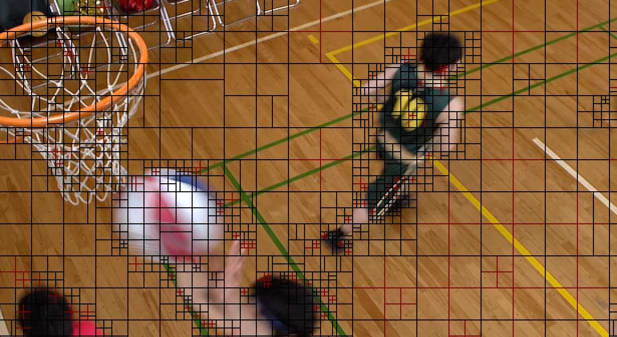
Fig 2. The shape, size, and position of the block to be predicted are adapted during coding to the boundaries, size and position of the objects in the video frame (Image obtained using the Elecard HEVC Analyzer software)
Lists of frames to be used as reference block sources for motion compensation
It is far from true that the image area yielding the best prediction for the current block is always located inside the closest video frame(s) in the video sequence that precede or follow the image being encoded. In this situation, the best prediction could be achieved by analyzing all previously encoded frames during motion compensation processing. This approach is clearly impractical because it requires virtually unlimited memory capacity to store the decoded images and virtually infinite time to search them for the best reference blocks. Modern video coding systems generally use a compromise approach. For each video frame to be encoded, they create a finite list of video frames that can be used as references. The encoding system then adds information about the content of this list to the encoded video stream.
Motion vector prediction
Each block encoded using inter-prediction should be accompanied by information about one or two (in case of bi-directional prediction) motion vectors. Sometimes the amount of this information is comparable to or even exceeds that necessary to describe the residual signal. To curb the amount of motion vector information in the encoded stream, modern video coding systems make extensive use of motion vector prediction methods. When these are used, the decoding system calculates the prediction vector, mvp (from Motion Vector Prediction), according to a known algorithm. Only information about the difference vector defined as the difference between the motion vector and its prediction is then added to the encoded stream. These difference vectors are called mvd (from Motion Vector Difference).
April 5, 2018
Read more:
Chapter 1. Video encoding in simple terms
Chapter 3. Spatial (Intra) prediction in HEVC
Chapter 4. Motion compensation in HEVC
Chapter 5. Post-processing in HEVC
Chapter 6. Context-adaptive binary arithmetic coding. Part 1
Chapter 7. Context-adaptive binary arithmetic coding. Part 2
Chapter 8. Context-adaptive binary arithmetic coding. Part 3
Chapter 9. Context-adaptive binary arithmetic coding. Part 4
Chapter 10. Context-adaptive binary arithmetic coding. Part 5
About the author:
Oleg Ponomarev, 16 years in video encoding and signal digital processing, expert in Statistical Radiophysics, Radio waves propagation. Assistant Professor, PhD at Tomsk State University, Radiophysics department. Head of Elecard Research Lab.